
It’s about time I had an update! This is basically skipping to the end from the last post, building cables, but I’ve been pressed for time in getting them built so I didn’t keep blogging as I went. I have a few pictures of putting the cabinets together, but it’s boring. I didn’t design that part, and I’m not a master craftsman with fancy insight into how you’re supposed to do woodwork. Hopefully the amplifier is a little more interesting.
The LX521 is a four-way speaker with an active crossover, which means that a pair of them need a total of eight amplifier channels. In order to provide uniform sound, all eight channels need to be identical. The amplifier that the designer uses is the ATI 6012, a 73 pound monster that costs about $2800. It’s an excellent piece of gear, but I was trying to keep the budget a bit more reasonable. A pair of Outlaw Audio Model 5000 could have also worked for about $1200 total, but then I’d need to put two 50 pound amps someplace. For just a little more than that I was able to put together a 25 pound amp that keeps everything in one box, and theoretically measures a little bit better. Also, I think that the more you build for yourself the more fun it is!
The amplifier I put together is based on a Hypex UCD180HG class-D module. I couldn’t really figure out precisely what their fancy voltage regulator upgrade would do for the sound, so I skipped it. If you have a dedicated listening room with soundproofing and are *really* into this stuff, then maybe you can give them a try (or go hog wild building with the Ncore modules). Now that I’ve built it I realize that this is dumb, but I used two of the 1200 watt switching power supplies, the SMPS1200A180. There is no way in hell I need that much power. Maybe I could throw a rave some day, but for now it just means that I have a bottomless pit of reserve power that I’ll never touch. By my best estimate, as loud as I’ve turned it up I don’t think I’ve used more than a few dozen watts yet. Hey dad, that means you could run these off of a solar panel pretty easily!
Anyway, on to the case and construction! I used the Modushop Mini Dissipante as the basis for the enclosure. I did some calculations of waste heat and fin area and all of that, and I must have messed up a decimal place or something, because I definitely didn’t need all of that cooling area. Oh well, I guess the parts will just last longer since they run cool.
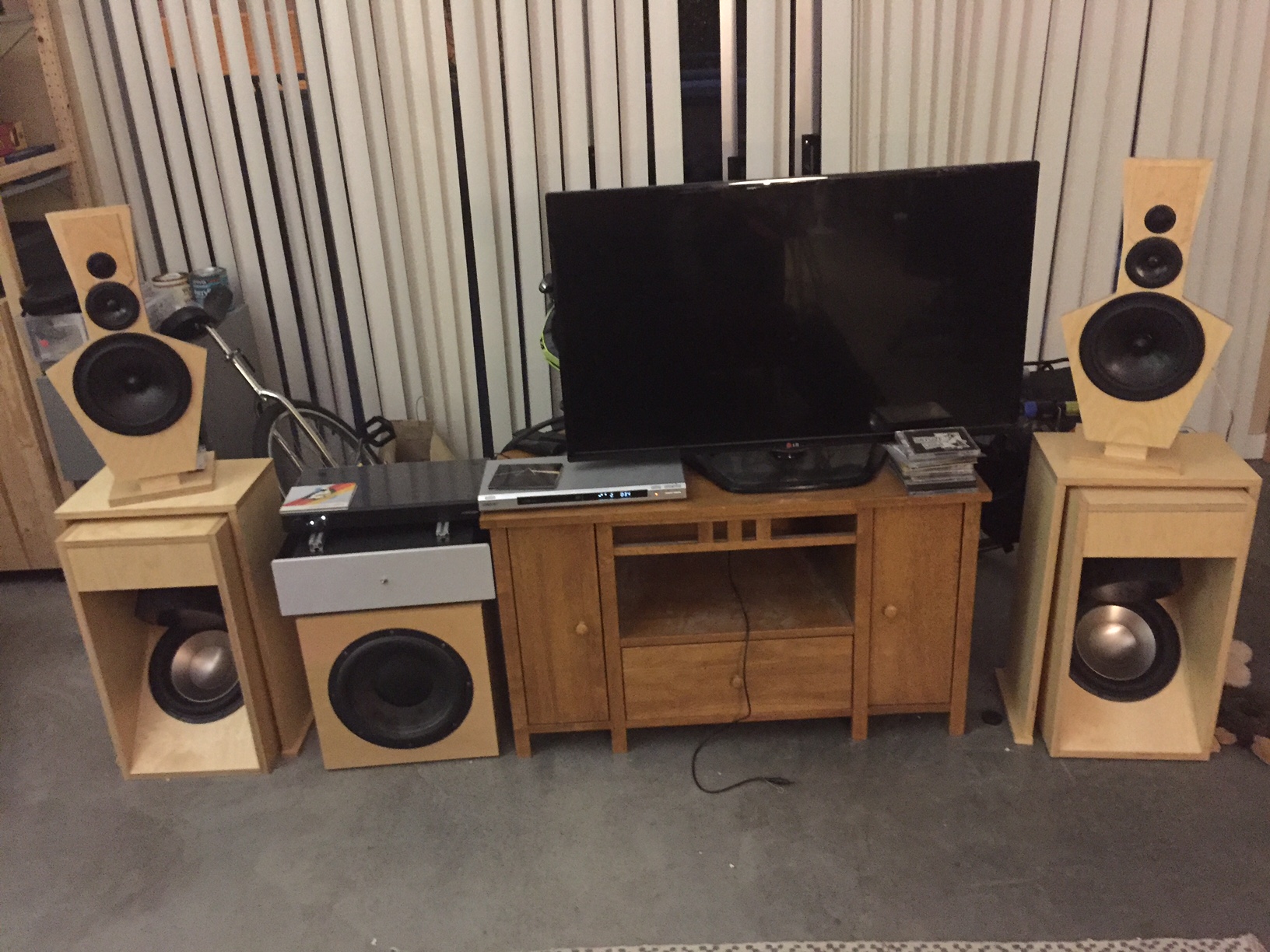
The finished amp looks like this in my living room:
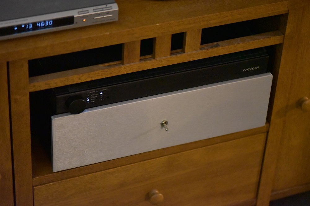
It’s just a plain aluminum panel with an on/off switch. Minimalist, right? The next step will be to make the guts look so nice.
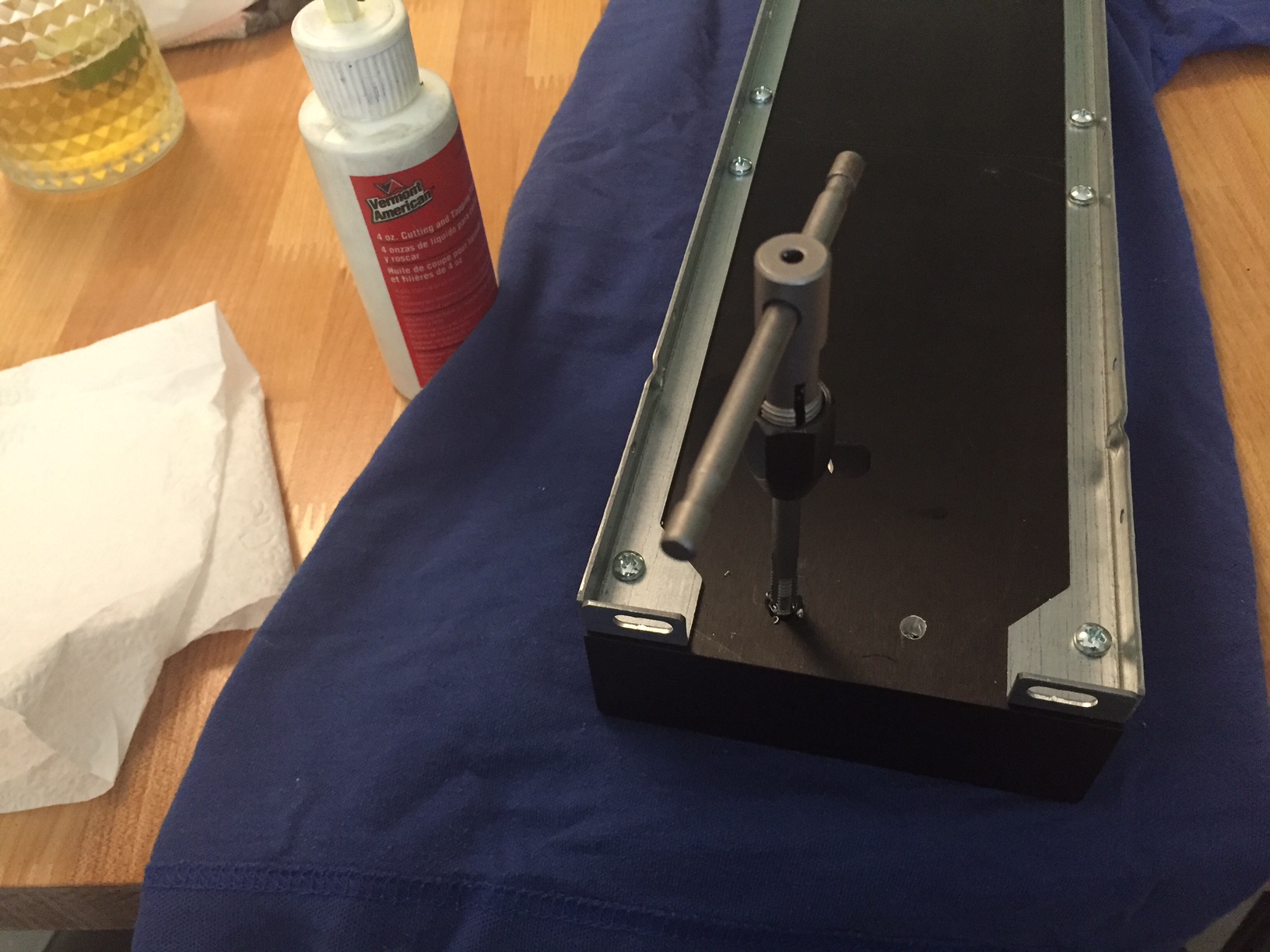
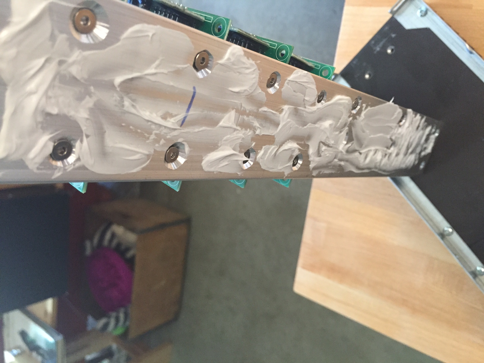
The amp modules have a blue aluminum T-shaped piece with two M3 holes tapped in it. I decided to put all of the holes into an interface plate, and then bolt the plate to the heat sinks. First I drilled and tapped some holes in the aluminum heat sinks, as shown here: note that I used an old T-shirt to protect the kitchen table, and the glass of beer with a lime in it was in fact a mexican style beer by the local brewery, 21st Amendment.
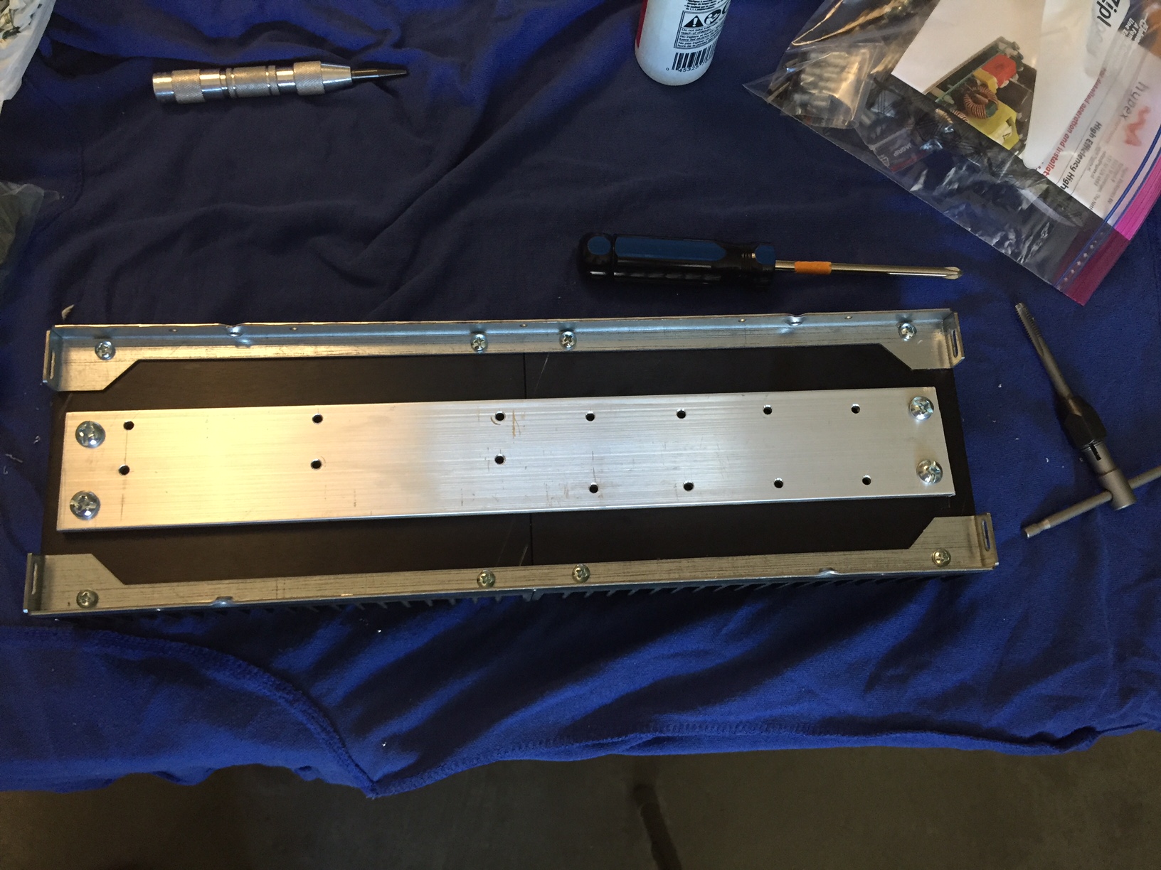
Next I laid out the interface plate using some calipers and an automatic center punch to give even spacing. You can see that tool in the upper left corner of this picture. This is really useful for achieving a medium level of accuracy in an apartment with hand tools. It’s not like when I had a techshop membership and would do this stuff on a mill, but it at least keeps the hole positions accurate enough that I can generally get them to line up.
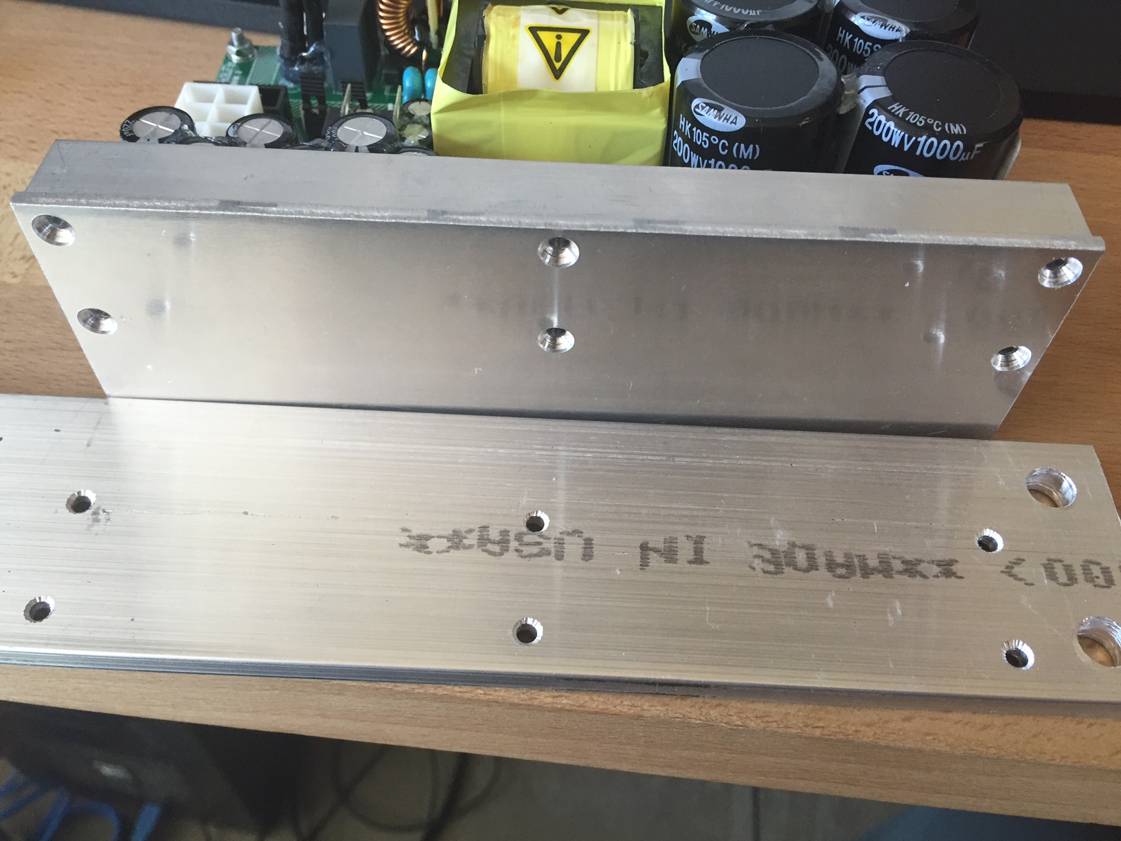
There are two 1/4-20 pan heads at each end of the interface plate, and if this were going to have a really significant heat load then I would have used more of them (and a different head) to ensure solid contact along the full length of the heat sink base. It was reasonably convenient though, and I’m not producing that much waste heat, so i thought it was a corner worth cutting.
The power supply module comes with six M3 screws already installed, holding a compression piece against an L-shaped plate. You have to take these out in order to have access to tapped holes to get this face against the heat sink interface plate. You could mount another way, and the manufacturer even says you can just let this thing hang out in free air, but I know that if I keep things cool they’ll last longer (like to pass down to my kids some day).
The amp module is surprisingly small for something that can do 180 watts and drive a one ohm load. I slathered on the heat sink grease before attaching them to the interface plate.
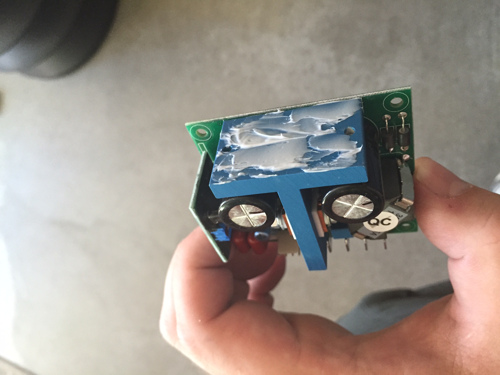
Once they’re all mounted it’s ready to mate up with the heat sinks assembly. You might be able to see that I did some really rough and rowdy countersinks to get those M3 screws to sit flush below the surface of the interface plate. I have some slight concern that some day one of them could be pressed against a capacitor and wear through from vibration and short something out, but probably not. I’m just documenting that concern in case anybody cares, and as something to think about for next time.
I know you wanted to see this all greased up. Look at those nasty countersinks! Eww!
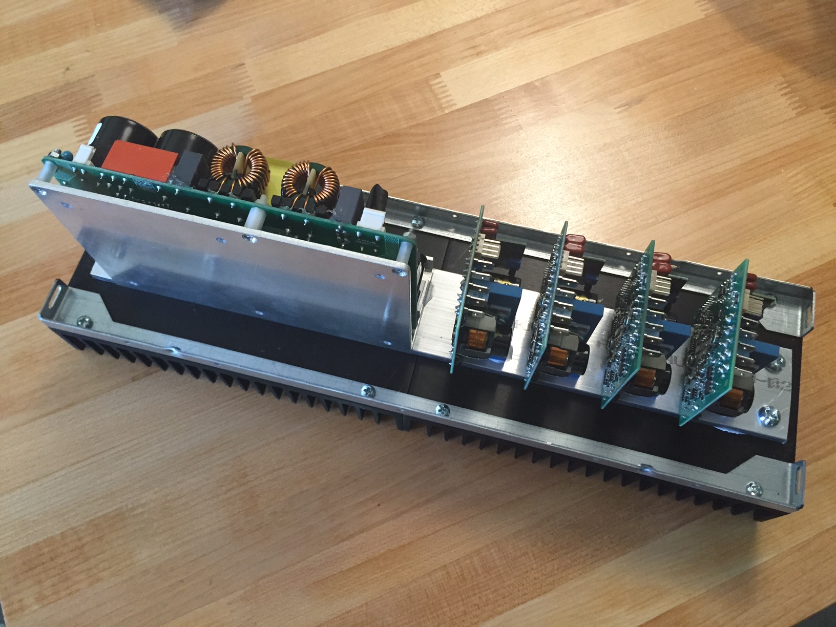
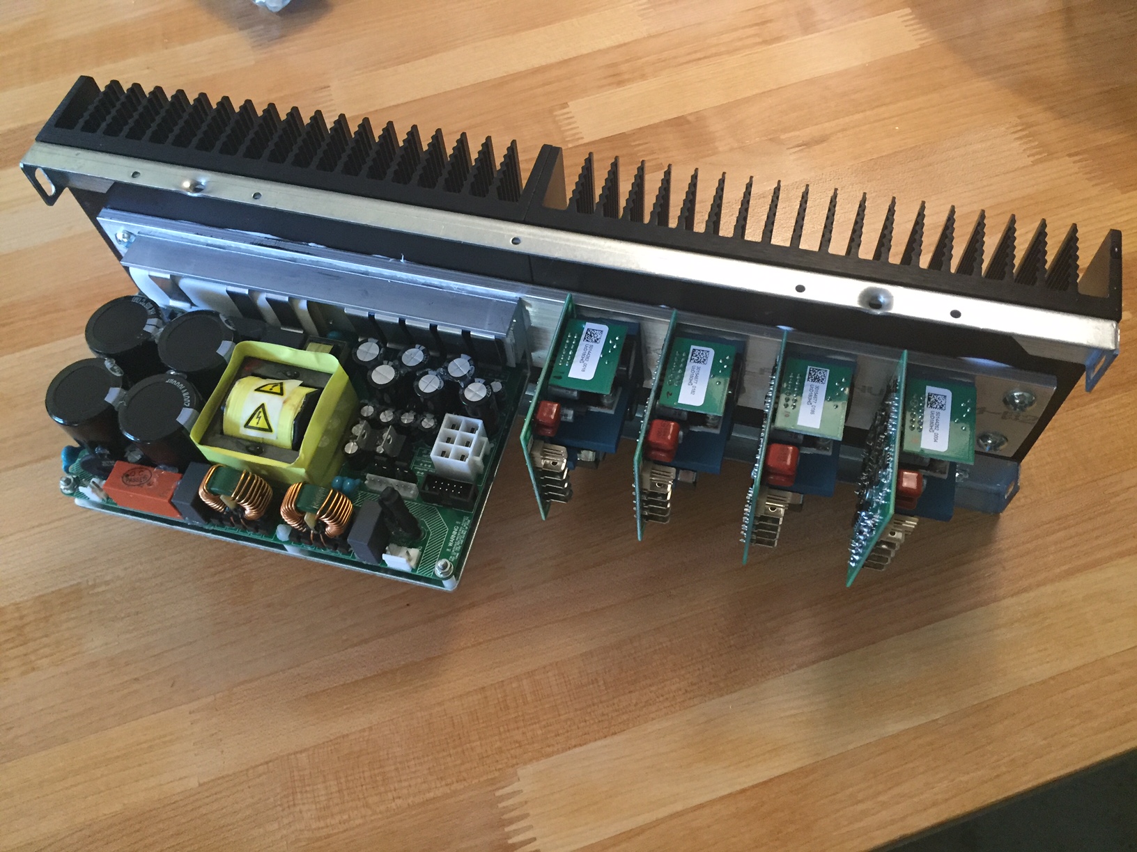
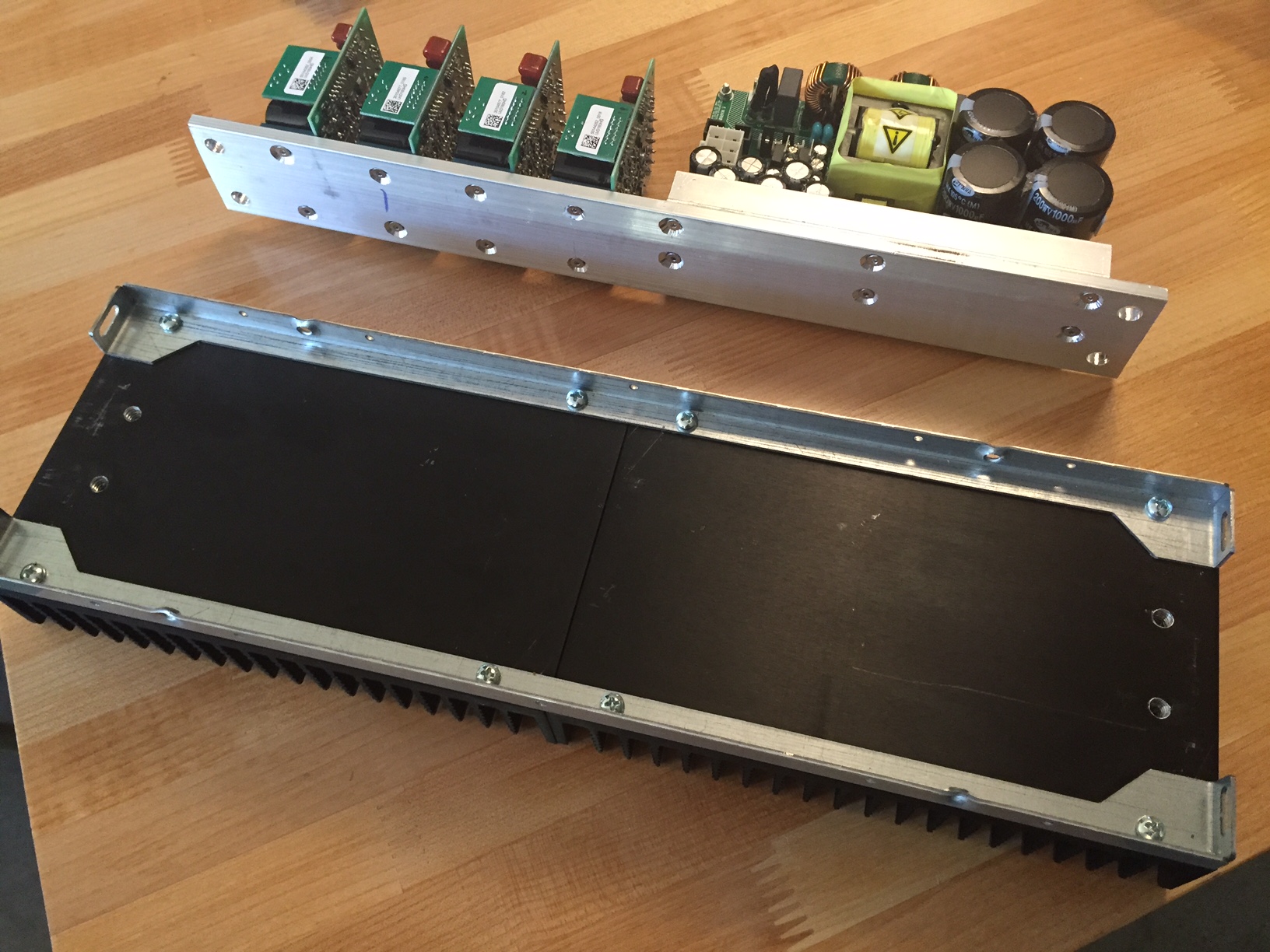
There it is! Four 180 watt modules with a 1200 watt supply, all ready for assembly.
And…. Oops. I built them the same, and that’s not going to work for wiring. I had to redo one of these.

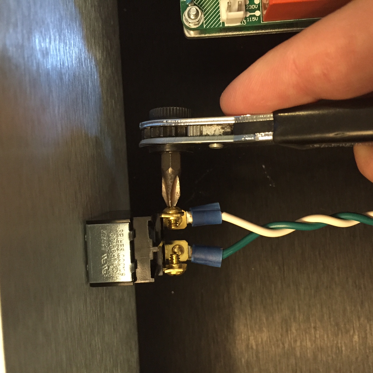
This is a really useful tool that I wanted to take a minute to talk about. This is a ratchet offset screwdriver, and it lets you reach into tight spaces that a regular screwdriver can’t reach. A well designed product won’t require this, but sometimes the designer just can’t be bothered to think about tool access… so that’s when you break this out. The best one I know of is what they used to work on medical linear accelerators at Siemens, and it’s the Chapman. You’ll notice that compared to mine, the ratchet area is much smaller, and the divisions between ratchets are signficantly smaller. That lets you reach into smaller spaces and tighten screws when you don’t have space for much rotation.
This is how I connected the mains power to the front panel toggle switch. It’s a DPDT switch rated for 20 amps, and I made sure that it was large because I wasn’t sure what kind of inrush current the power supplies would draw. As it turns out, they seem to have a nice polite soft-start, or else their inrush is much smaller than the spec sheet indicated because they’re just getting US voltage instead of the 230V that europeans are working with.
This ended up being a little easier than I expected. The power supply sends a few leads over to the terminal blocks, and each amp takes a positive, negative, and ground input for power. The worst part was all of the crimping. I think I ended up doing about a hundred crimps. There’s a reason they make machines to do that.
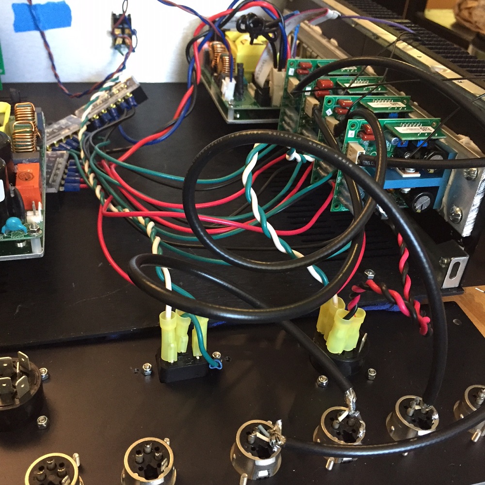
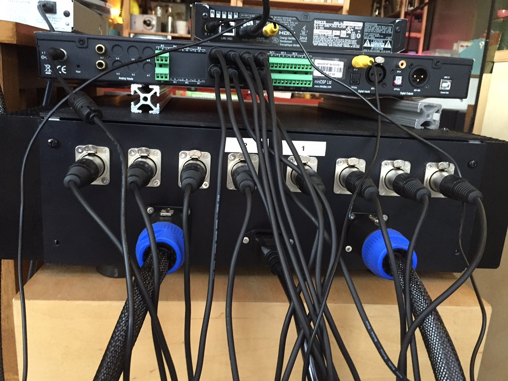
In the lower right of this image you can see the twisted pairs of wires going to the speaker output jack, and the black cables soldered directly to the XLR jacks. I need to go back and get everything twisted and trimmed more appropriately before I’ll say I’m done, but for now it works.
The last thing I did was put channel numbers on each of the amps so that I can keep things straight, and I checked a test signal on each to make sure it wasn’t putting out a measurable DC voltage and a full range music signal sounded right with one of my old speakers. During this step it was really promising to hear music coming out of my old speaker that (I think!) sounded better than the eight year old cheapie receiver that had been driving them.
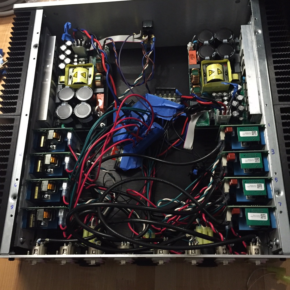
One thing you’ll notice here is that I used blue paper painter’s tape as a temporary measure to keep anything from shorting out. The maximum voltage in here is 48 volts relative to ground, and 96 volts from the positive to negative terminals. Everything is firmly connected to screw terminals inside of insulated blocks, but a little bit of metal peeks out at the edges, and so I didn’t want to take any chances on something shorting out. The end goal is to have the terminal blocks bolted to the bottom panel of the enclosure in a neat row so that the wires can be routed in a clean and proper way.
The 120V mains line goes to the switch on the front panel using a tightly twisted pair of 14 gauge wires in some ring terminals. I used fork terminals for the rest, but for 120VAC I used insulated ring terminals so the screw would have to fall completely out before the crimped part could fall and contact something else. The rear panel has a three-prong jack, and there’s an earth ground that’s similarly connected to the chassis (you can make that out in the photo above).
The back of the amp looks fairly neat thanks to Front Panel Express making the panel for me. The large cutouts in thin aluminum and added threads saved me a *ton* of work, and I know they made it look nicer than I could have. I’ll add more labels when I’m done, but for now I know how they’re laid out well enough that a prompt of “1” and “2” is enough that I won’t plug something in wrong. If I did do that, it would blow up my tweeters.
Ok, so that’s all I’ve got for now. I’ll leave you with a cell phone picture of the speakers and amp in the living room. They sound pretty good. I hope you’ve enjoyed reading!
Thanks so much for linking to our website! I’m the marketing guy at Chapman, and I didn’t know that Seimens uses our tools on medical linear accelerators. If you have a minute I’d love to chat with you, please e-mail me at joel@chapmanmfg.com
Thanks, Joel
PS: Nice build, I really like the single rocker switch on the face of the unit
Great article, one of the kind as I have not found any other guide to building the hypex ucd180 amps!
Would you mind posting up a list of secondary parts required (cables, connectors etc).
Also, is there a reason why you chose balanced inputs as opposed to unbalanced (RCA)?
Thanks Daedalus, I’m glad you enjoyed it! There are a few builds out there; I found that doing a google image search let me find them more easily than a text search.
Unfortunately I don’t have a handy list of all of the auxiliary parts, but if there are any bits that you see that don’t come from Hypex that you can’t find or don’t know the name of, just let me know and I’ll try to track those down for you.
The reason that I used the XLR connectors is the Hypex amp is expecting a balanced input, and what I’ve been able to read suggests that the best performance comes from doing the RCA to XLR conversion at the chassis wall, or outside the box. I would have run balanced wires all the way to the MiniDSP, but I found somebody doing measurements that show that the MiniDSP unbalanced output is probably lower in noise and distortion (at the levels we use it for the LX521) than the balanced outputs. If the gain structure was different or if I was running a long signal wire from the DSP to the amp then balanced would have made sense, but as it is I’m just using the RCA outputs and doing the conversion with the cable.
Here’s where I found that measurement:
http://www.neurochrome.com/minidsp-4×10-hd/
Hi, thanks for writing this up, I was thinking about doing the same thing for my LX521s, but it surprised me that you went with 8 channels instead of 10 given SL’s specification for an amp for his 4-way version of the speaker:
“the LX521.4 would take 10 amplifiers. A separate amplifier channel is allocated to each of the 10″ dipole woofer drivers to obtain output capability that is commensurate with the midrange, yet minimizes bottoming and the risk of mechanical damage to the woofers, or having to reduce the speaker’s low frequency extension.”
It would be nice to drive both woofers off a single channel, since adding a 5th channel is going to make it so you can’t use those nifty sspeakon connecters. Curious to know what your take on this is, why did you go with 8 channels instead of 10 and in what circumstance would you have gone with 10?
Hi Eric, I’m glad you liked the post! I gave it a lot of thought when I used eight channels, it wouldn’t have added that much more cost as a percentage of the system and I intentionally left room inside the housing in case I wanted to add two more channels. However, after a lot of reading on the support forum with examples of other people who used four channels, and an explanation that the woofers don’t really need that much power in the range where they have the lowest impedance, it really looked like it was going to be OK. Not all amplifiers can handle a 2 ohm load, but the Hypex can! If you are using class AB amps, I’d say that it’s a good idea to use ten channels.
As a subject matter dummy, I’m trying to figure out if I’d be able to pull off doing this myself. It looks pretty straight forward, but I do have a few questions.
J3 – Mains Voltage Selection.. I see that you have set this closed for the 115Vac selection, and I will need to do the same. It looks like you used a hookup wire to do this? Are those wires soldered or just in contact?
J4 – UcD/NCore interface – As far as I can tell this isn’t used for the UcD180 amps, but you appear to have ribbon cables connected anyway. What for? Are you grounding J4.3 and or J4.9 or something? Is that necessary or can I just leave the ribbon cable off?
J1 – J1.1 and J1.4 are described as “bootstrap driver voltage” which is described in the data sheet as such:
“The SMPS1200 provides a regulated Bootstrap Driver Voltage (VDR) which is used to power the driver circuit of an UcD or NCore series amplifier. Most Hypex amplifier modules need the VDR voltage referenced to the negative supply rail (HV-). In order to achieve this, the VDR- should be connected to the main negative supply rail (Hv-) at the amplifier side. The VDR+ must be connected to the UcD/NCore series VDR supply input.”
However, it does not look like you are connecting these? It looks like you just cut them short and taped them? Is this because the UcD180 doesn’t have this “driver circuit”? I don’t know what that means.. and bootstrap to me suggests some sort of start up process?
Parts unknown:
What are the parts you’re using to “fork” the positive and negative and ground DC rails? I don’t even know if my terminology is correct but hopefully it makes sense… I think I need to acquire these but they do not appear to be available at the hypex webshop and I wouldn’t know how to search for them at a general parts shop because I don’t know what they’re called.
Lastly, it’s not super clear to me how to hook up the AC power to the power supply. I’m guessing this is pretty straight forward, I just need a part that allows me to plug a power cable into my case which then hooks into the brown/blue cables supplied by hypex – which if I’m not mistaken brown in Europe is hot and blue is neutral.. optionally I can run the circuit to the front plate for a switch like you have.. I guess I’m curious about a parts list to complete this part? Or at least some guidance on how to search for it and understand if I’m doing it right or if I’m going to burn down the neighborhood…
I really wish there was more hand-holding guides for hypex in english.. I think I found some in German, but that doesn’t help me! This looks really simple and fun, but there’s just a few bits of info I’m missing.
Thanks for your help!
Hi Eric, I’ll have to refresh my memory a little bit, so please double check anything I’m about to say!
For J3, I did use hookup wire, but I used actual crimp connectors inside of a plastic housing, so it will remain a sound electrical connection. I believe they supply the housing and contacts in the harness kit, and it could be used to connect to a switch on the exterior of the housing. I don’t think DIYers would need that, but if you’re making an amp to sell or give to someone else, that would be handy.
For J4, I *believe* I’m using pin 5, “enable” and connecting that one wire to four UCD180 modules, their soft on/off switch that’s included as the fourth wire of the signal cable. The intent here is to prevent any turn on/off transients, which is especially important for protecting speakers with active crossovers. I wish that I had documented this better, but I think that I did it right.
You’re correct about the J1.1 and J1.4 being cut off and taped for isolation. I also don’t understand what they’re for, but I think that I read on a forum that an earlier/different module needed them. Evidently the UCD180HG does not need them.
The part you’re referring to as a “fork” for the DC rails is probably the terminal blocks. Here’s an amazon link: http://a.co/5k2gLDh They’re simple enough that you can make them from scratch as needed by drilling holes in a copper bar, but then you need to insulate and support them, and the ones I found were pretty cheap and durable, plus they’re rated for significantly higher voltage.
As a point of safety, I ran the mains power to a heavy duty double pole double throw switch (amazon link: http://a.co/iYRkRQo ), and from there it went to the power supplies. This means that when I flip this switch, the power stops at the switch regardless of plug polarity. I wasted some time and effort trying to figure out if I needed a soft-start circuit, or needed to worry about surge current on the switch, but I’ve never seen nearby lights flicker when I switch the thing on, and I might have even broken out my clamp meter to look for peaks- I didn’t write a value down, but now I’m satisfied that the switch is more than adequate.
I agree that it would be great to see more detailed guides out there, but I didn’t really feel like the authority to put one together! I’m happy with the results, but don’t know if I narrowly avoided any pitfalls.
One thing I’d tell you- this Modushop enclosure runs ice cold, and so I say that the fins are massive overkill. The space provided inside is just about perfect, but if there’s an option with smaller fins I’d definitely consider that. Another thing, I didn’t get the HxR regulators, but kind of wish that I had so that I wouldn’t waste time worrying about if I’m missing out on some audible benefit from that marginal increased cost.
Hope that helps!
Wow thanks for the J4 tip – I had no idea. Well, if I go forward with this I’ll get the HxR regulators .. seems to only add 240 euros to the cost, and that’s marginal given the entire investment in the speakers dsp and amps.. If you’re interested I can let you borrow my finished amp to see if you can hear any difference, as a thank you for helping me get stuff figured out. I’m guessing you’re in the bay area since you visited SL in corte madera. I’m in Sonoma County.
Hey Eric, I didn’t see this right away, that would definitely be interesting to see if we hear a difference with the HxR regulators! Drop me a line if you go for it and have it all wrapped up.