About a year ago I was contacted by a professor at UC Berkeley who had found my resume online. Her team had produced a backpack device that was capable of collecting data to generate 3D models of internal spaces, and she needed a new backpack designed that would be smaller and lighter. I took this on as a part time project while I was looking for full time work, and it was a fun challenge. I’ve talked about this project in the past, but they finally went live with the backpack so I thought it was time for a post.
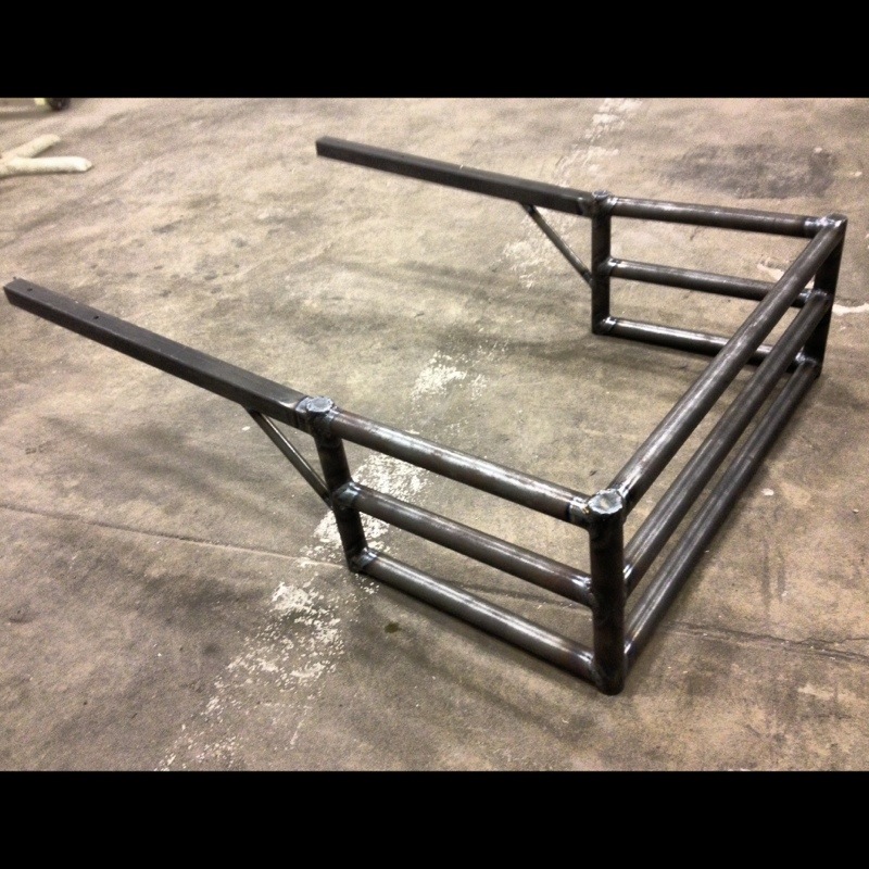
You can read all about Professor Zakhor’s original backpack on the EECS website. This is what they had before I arrived. It weighs over 70 pounds, is built to hold an changing array of sensors and cameras, and I understand that it went through many iterations and changes as they developed the software techniques that could turn the data into usable 3D representations of internal spaces. My job was to provide a compact, lightweight platform that provided stable and well defined positions for a suite of sensors. Many of the sensors needed to be adjusted to different angles to accommodate users of different heights, or movement through different environments.
The sensors on the version of the backpack that I designed include:
- Three Dalsa Genie TS series machine vision cameras (with F-mount adapters to hold ultra-wide angle DSLR lenses such as the Sigma 8-16mm)
- Two Hokuyo ULM-30LX laser scanners (which take 2D slices of the room many times per second)
- One Panasonic D-imager, pointing toward the floor to maintain an accurate height location of the backpack
- One Intersense Inertiacube4 3-axis accelerometer
- Four magnetometers
That’s it for now, but it’s possible to attach other pieces as needed. I sourced an embedded PC that seems to have the processing power to shove all the data from those sensors into some SSDs, and the entire collection of parts is powered by several lithium ion batteries. The batteries are an off the shelf solution, and have a good amount of intelligence and safety built in. We run the batteries in series to create a voltage from about 18 to 60 volts, and a DC-DC converter regulates this to a main system voltage of 24 volts.
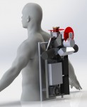
Here’s a creepy render of the system on a mannequin.

Check back soon, and I should have an explanation of what each of the sensors is doing, and how I designed this thing!