Since my last post we’ve moved and had a baby, who is now a rambunctious toddler. I’m getting to do some projects again so it’s time to bring the blog back!
This project might be a little more “totally should” than my other recent audio posts, so I thought I’d share some of the design process. This project started with brainstorming how I might build subwoofers for our new TV room.
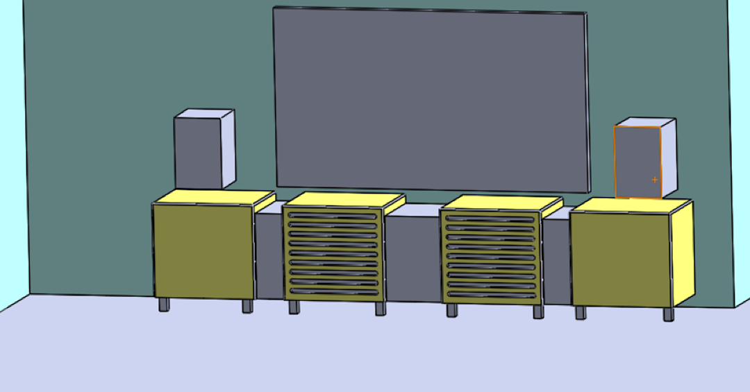
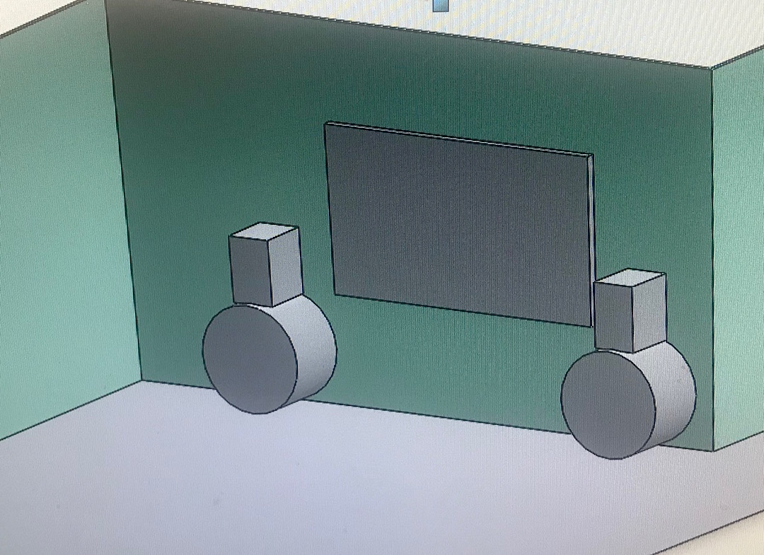
My first idea was to build some modular cabinets across the front, with sort of a repeating cube shape. It seemed neat, but didn’t leave a ton of flexibility for positioning things or experimenting with different speakers such as different center channels or larger left and right speakers. Here’s what it might have looked like.
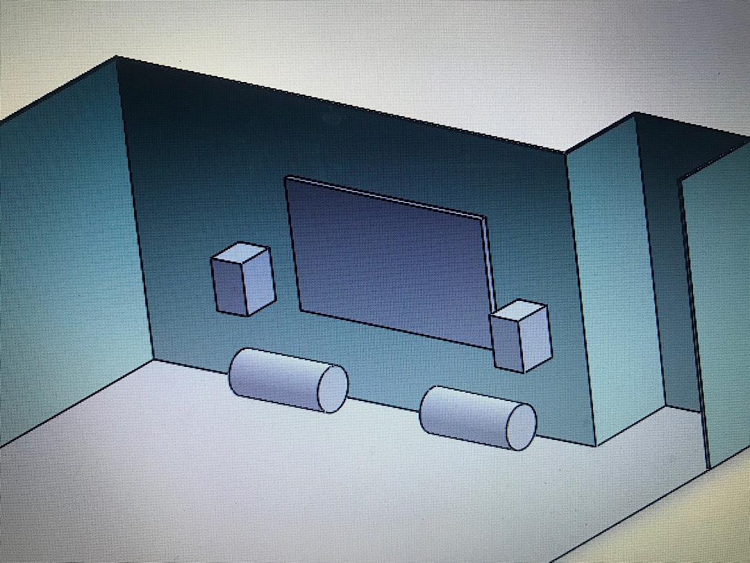
Next I had the idea to move the receiver elsewhere, and have just the subwoofers and speakers at the front of the room. An idea I had been thinking about for a while was to use pipes as enclosures since the curved walls are extremely resistant to flexing and re-radiating extra sounds that distort the output.
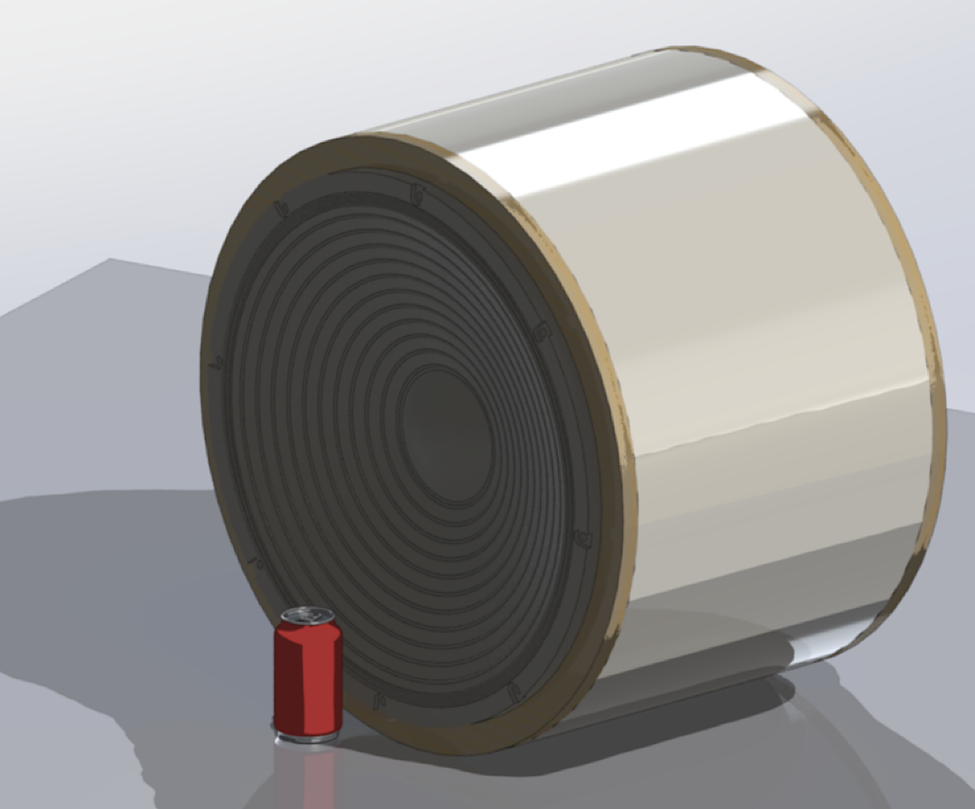
I was considering using two ten or twelve inch drivers in each pipe, using this Excursion calculator to see what the maximum sound pressure level might. THX reference is a peak of 115db at 30hz, and my goal was to be able to achieve that as low as 20hz. I found that four pieces of the Dayton Ultimax 12” woofers would be able to get close to this if they driven to their limit and had some help from room gain. A 14″ pipe would work for that, and would like something like this:
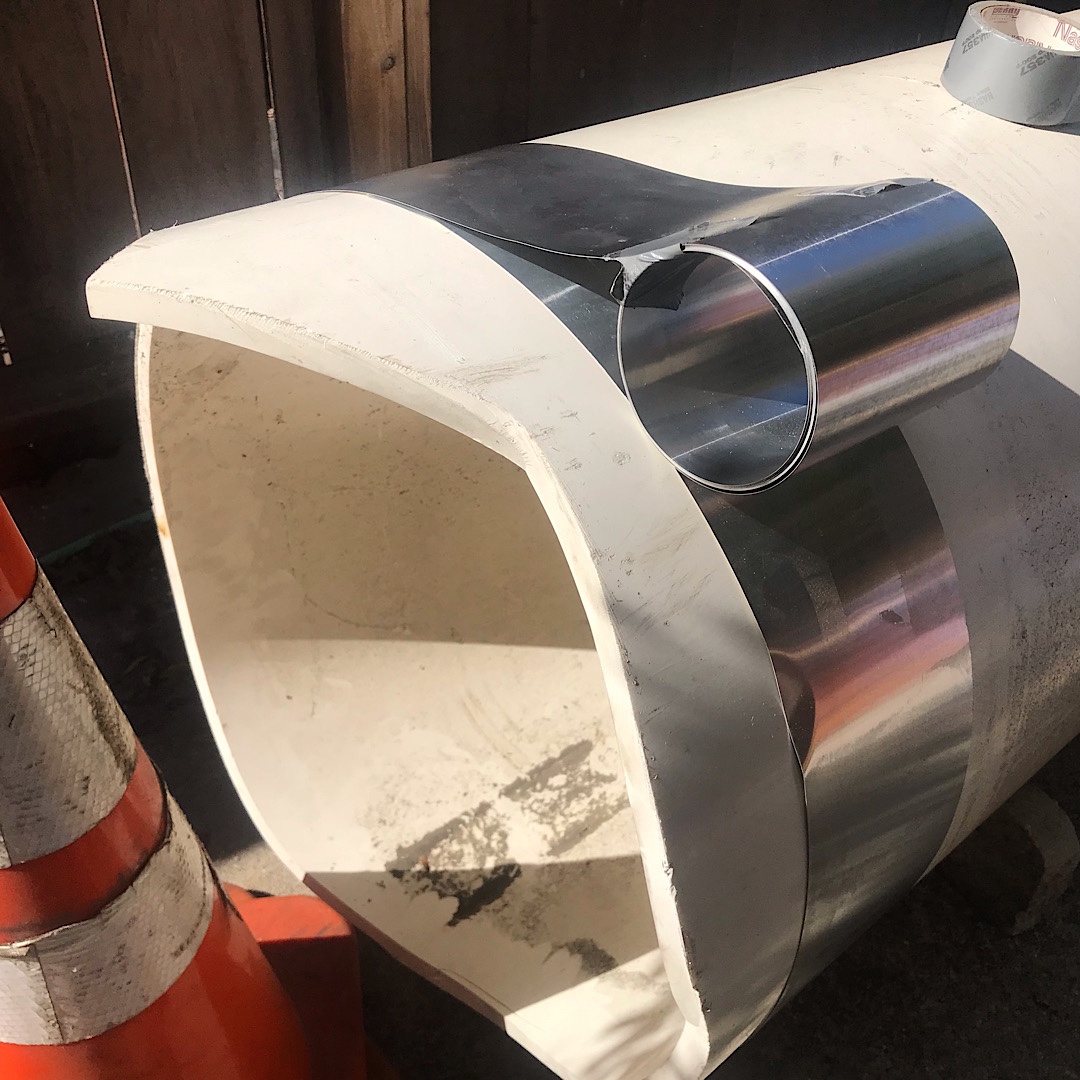
I started calling around looking for pipe, and it was hard! This stuff gets expensive and they only sell it in 20 foot lengths and won’t cut it. Finally I found a place with a broken piece of pipe in their scrap pile, and I could have it for free! But… it was 24″ schedule 40 and I had to figure out how to pick it up. I thought to myself, I totally should!
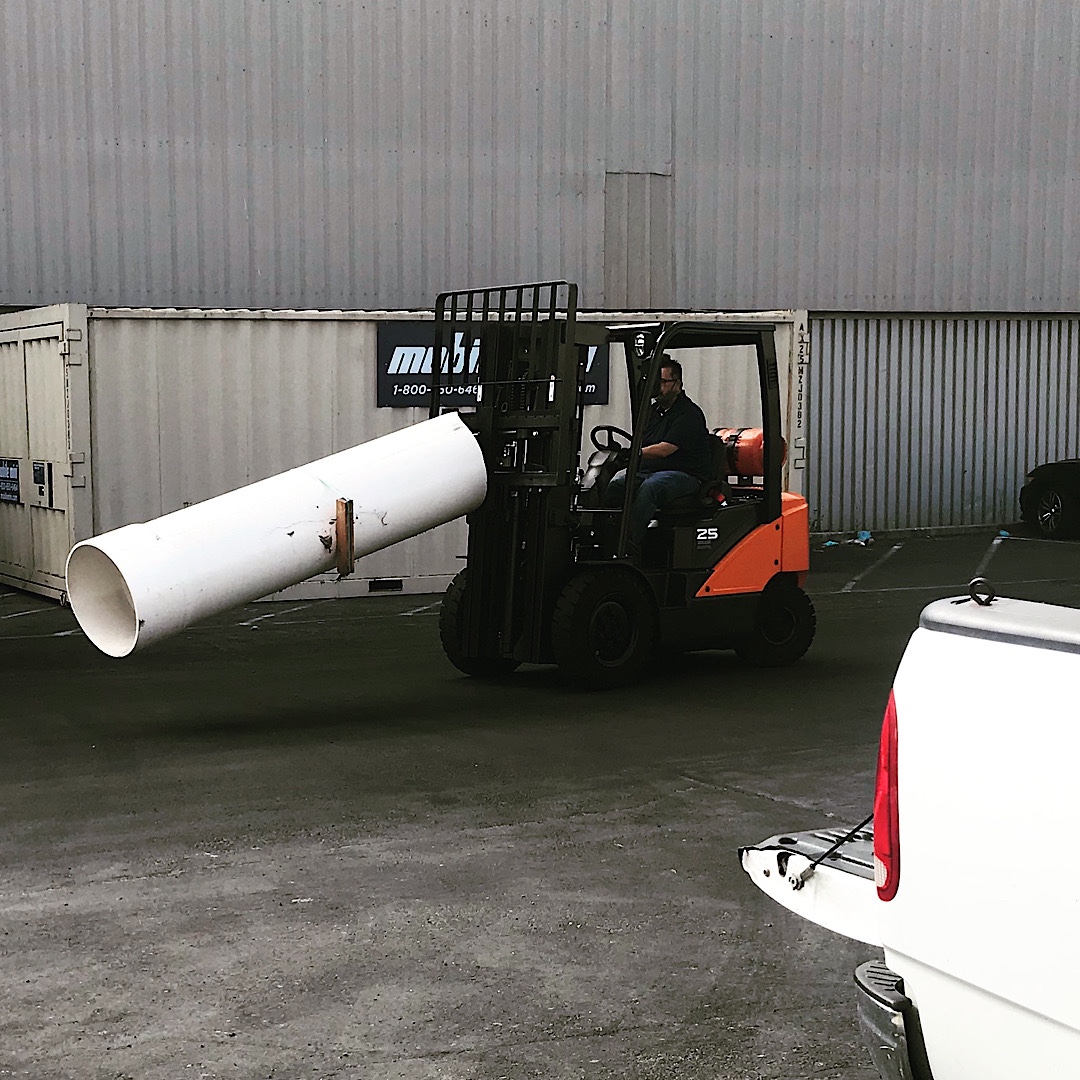
I called my friend with a truck and the folks with the pipe were kind enough to help us get it loaded. It was an amazing score, but I had to go back to the drawing board.
It looked like the pipe could hold as large as a 21” woofer fairly easily, so I did some more modeling with WinISD to see how much output I could expect at different power levels assuming different volumes and equalization filters. It became clear that I would have to spend a lot more on amplification to use most of the better 21″ drivers that would work in a small enclosure. I also noticed that the large moving mass might have the whole device dancing across the ground slamming into walls. The pipe weighs 32 pounds per foot and has a cross section of 2.77 square feet, so it would be feasible to make a relatively light weight sub with this stuff.
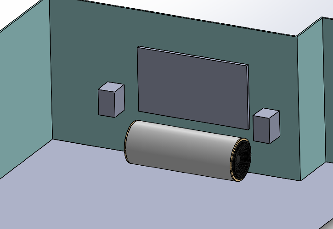
I played with the idea of putting the pipe right under the TV, but that really took up a lot of visual space and makes it much harder to use a center channel. The nice part of this iteration was that the dual-opposed woofers achieve force cancellation to keep the sub stationary (and reduce distortion), and the large volume allows sufficient low frequency output without requiring enormous power levels to overcome the stiffness of the trapped air inside the enclosure.
I selected the Dayton Ultimax 18” driver which was on sale and scaled the design to a pipe length of about 40″ long and nine cubic feet of internal volume. Based on room mode simulation in Room EQ Wizard as well as measurements with a borrowed subwoofer I decided that the sub could fit behind our couch and act as a second row of seating.
So how big is this pipe?!?
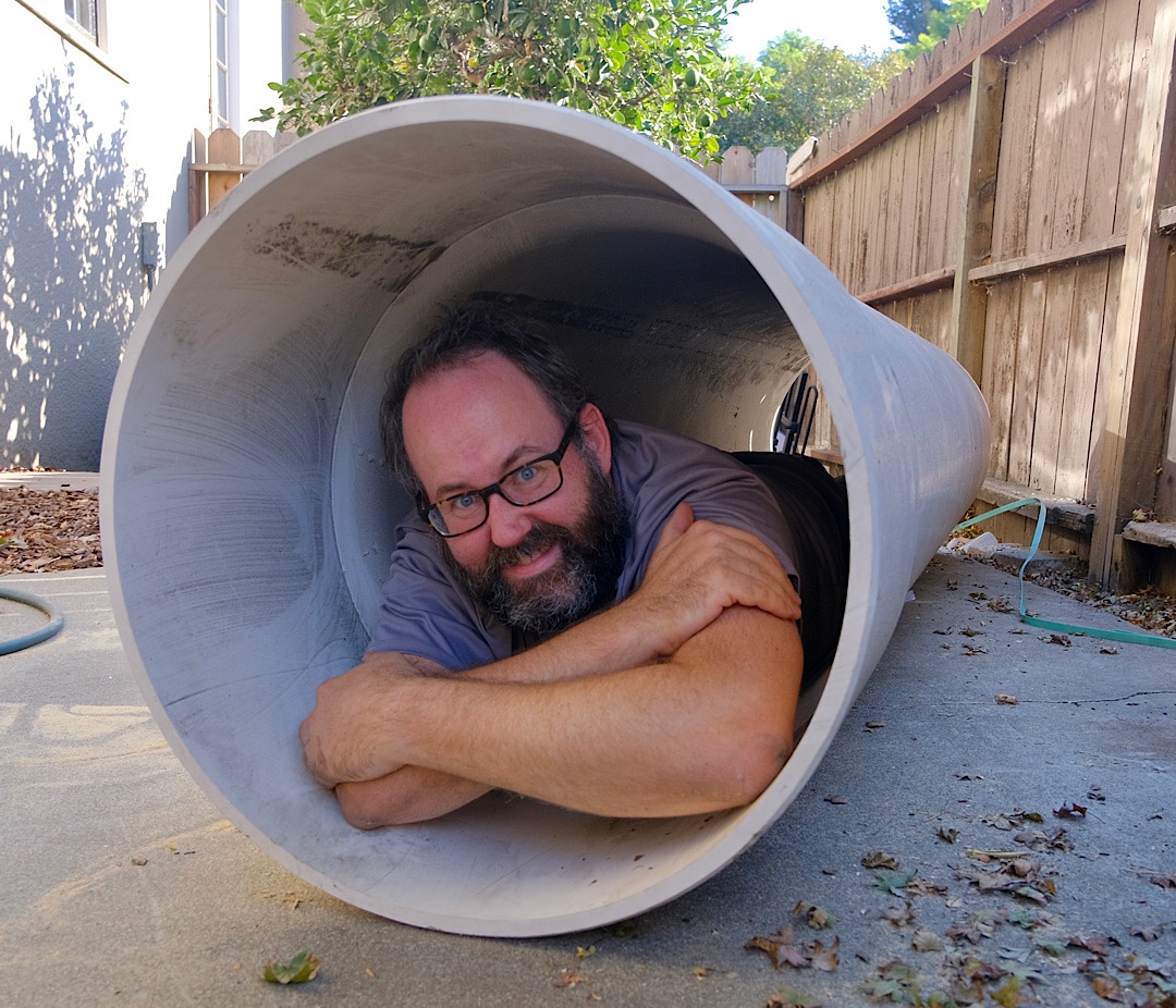
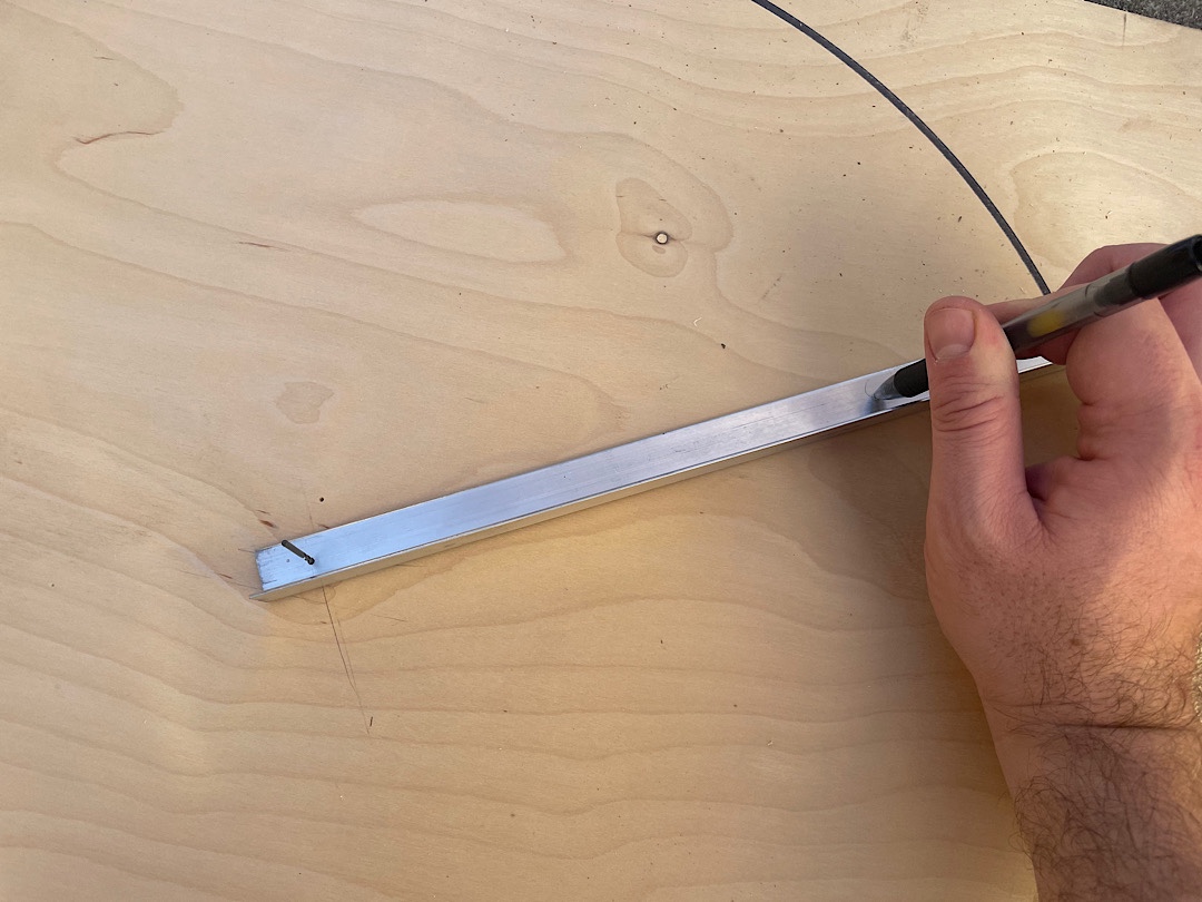
Really big. I had to use a jig saw to cut it to length and it took me about ten minutes per cut. I ended up using a piece of aluminum flashing as a flexible straight-edge to mark a guiding line for the cut. I guess a piece of twine pulled tight would work too, but this is what I did.
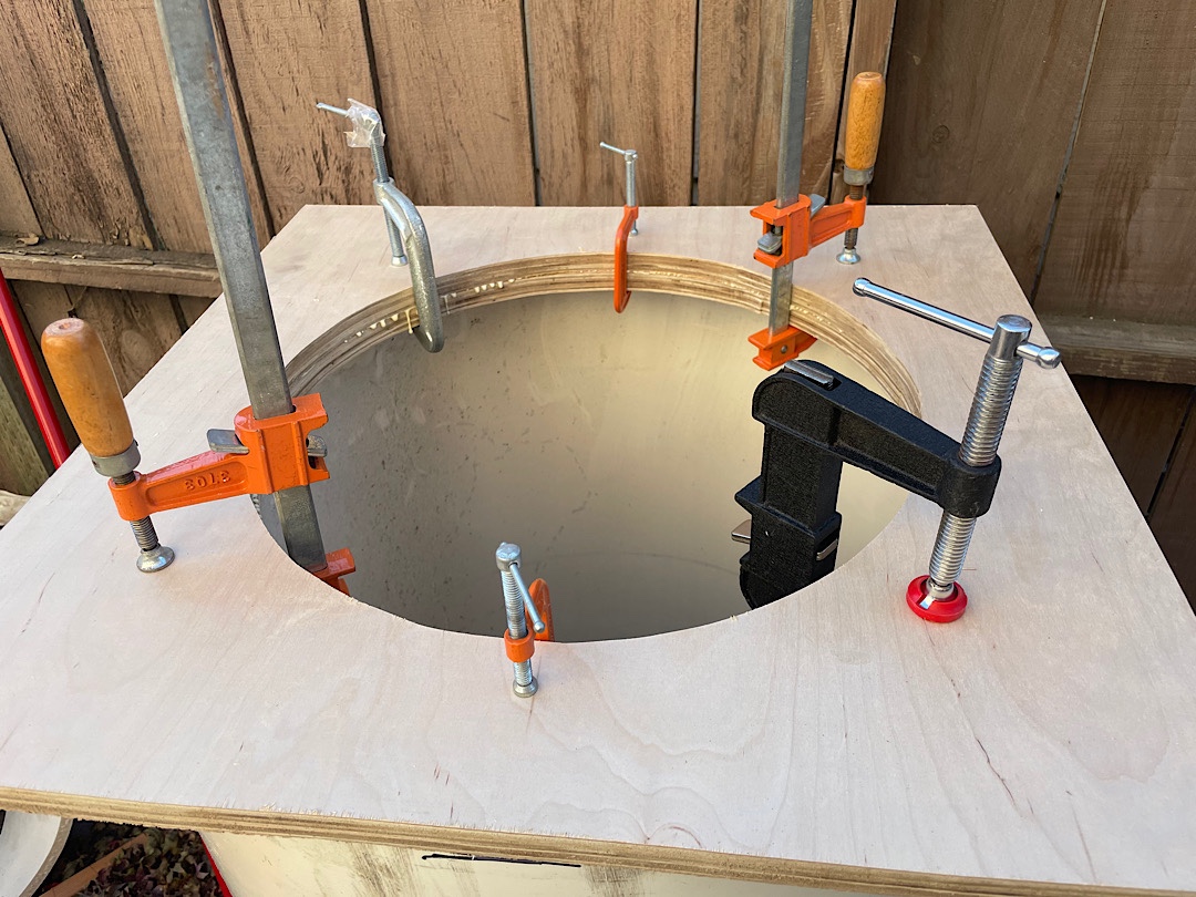
After cutting it to length I created some 1.5” thick plywood baffles to follow the axial and radial edges to create a large area for glue to hold the pipe in place. Here’s one flipped upside down so you can see what I’m talking about.
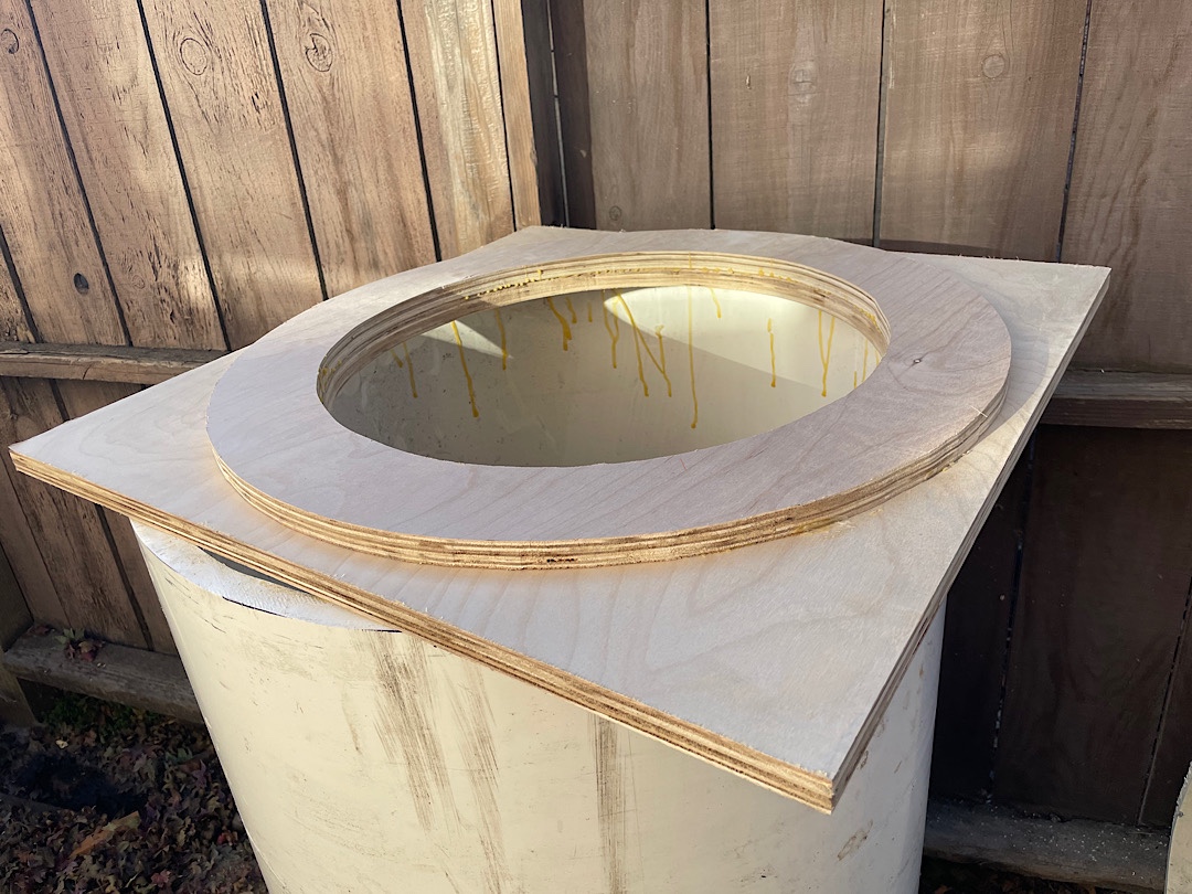
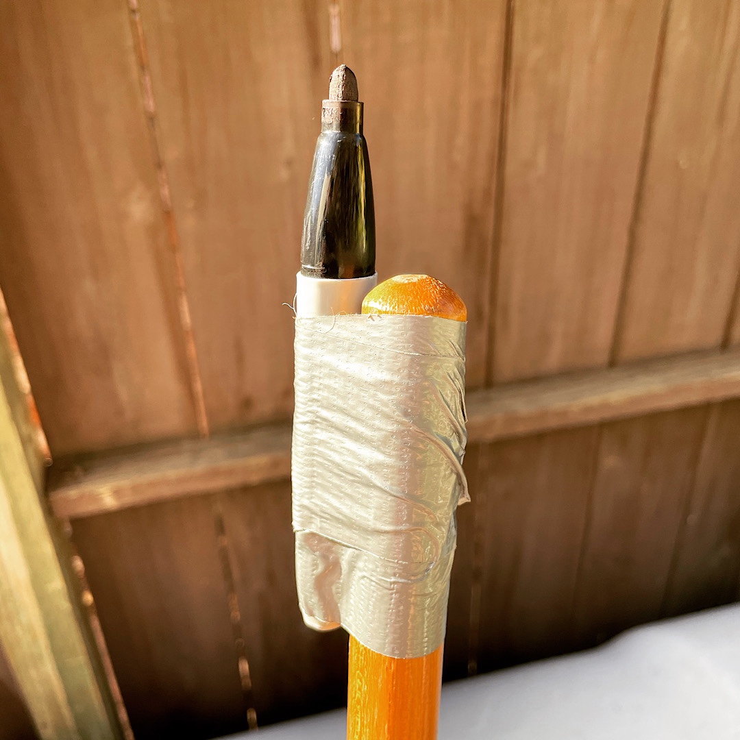
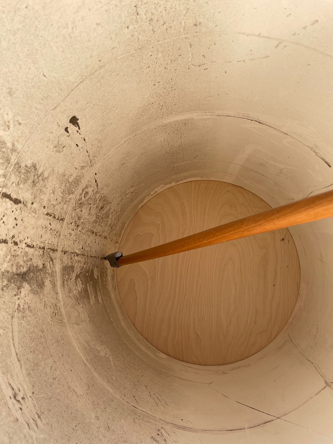
The pipe isn’t actually round though, maybe because it was damaged when it fell off the truck, maybe it was sitting around too long, or maybe that’s just the tolerance. Regardless, I used a sharpie taped to a rake to trace the actual contour. After making a circle jig for the driver cutout I glued the pieces together using the pipe to keep them centered and oriented. This was important since I wanted the square ends to stay aligned enough for the sub to sit flat on the ground.
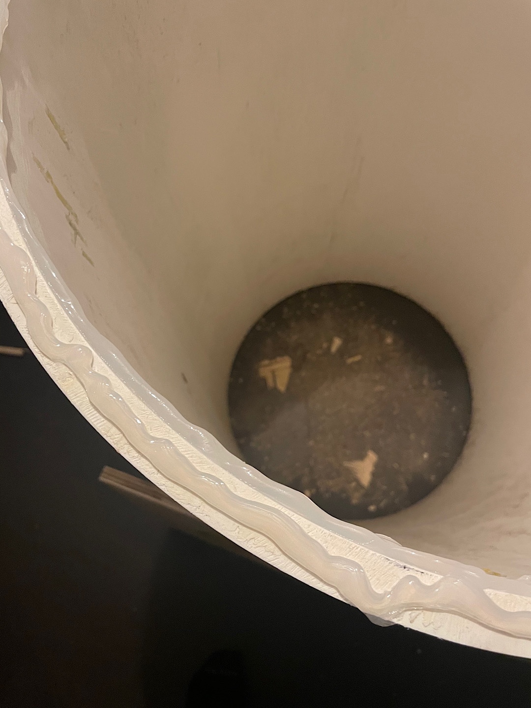
I had to go through several glue trials to find something that would stick to both the wood and the PVC. I found that liquid nails didn’t stick to the PVC hardly at all, and I ended up using marine silicone after roughing up both surfaces with 60 grit.
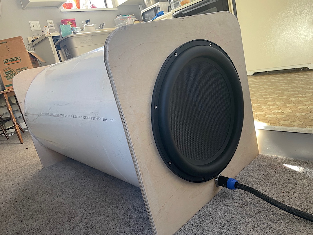
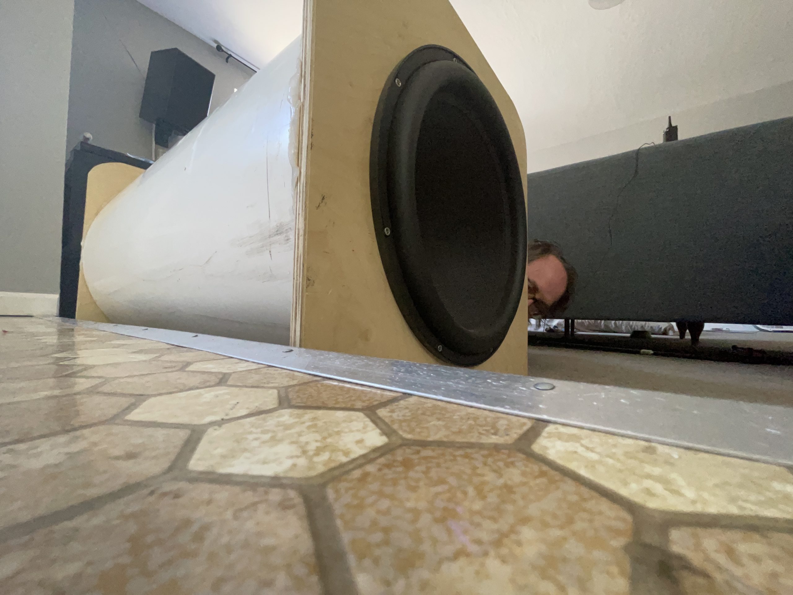
Skipping ahead to the end, I used a Neutrik Speakon four pole-connector, some hurricane nuts, and Ultratouch denim inside the enclosure to help absorb higher frequency resonances. It was a success!
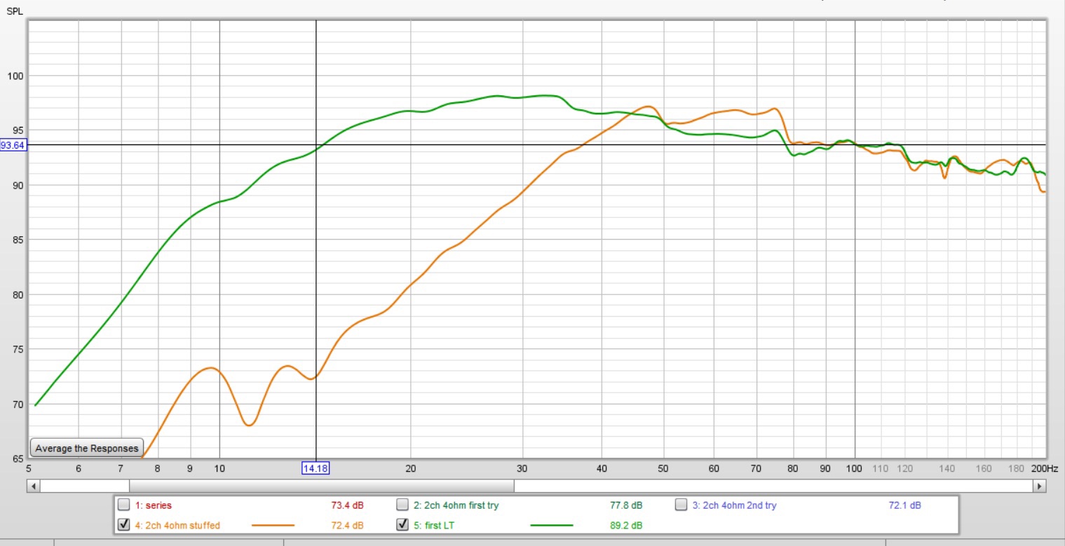
Next I needed to apply the Linkwitz Transform processing to get that wonderful low end. The brown trace on the graph is a close-mic measurement of the sub with zero processing. The green one is with the Linkwitz transform applied in a Minidsp 2x4HD. The in-room response is strong to below 10hz now, and the subwoofer is very hard to localize behind the couch. I think that this is due to the nonexistent structure borne resonance and lack of spurious noise and distortion. It could theoretically play at least 10db louder than a push it for movies, and I think that’s very helpful for preventing the kind of misbehavior that draws attention to a sub.