Lasers, sensors, cameras! A 3D scanning backpack for UC Berkeley (part 1)

Lasers, sensors, cameras! A 3D scanning backpack for UC Berkeley (part 1)

About a year ago I was contacted by a professor at UC Berkeley who had found my resume online. Her team had produced a backpack device that was capable of collecting data to generate 3D models of internal spaces, and she needed a new backpack designed that would be smaller and lighter. I took this on as a part time project while I was looking for full time work, and it was a fun challenge. I’ve talked about this project in the past, but they finally went live with the backpack so I thought it was time for a post.

You can read all about Professor Zakhor’s original backpack on the EECS website. This is what they had before I arrived. It weighs over 70 pounds, is built to hold an changing array of sensors and cameras, and I understand that it went through many iterations and changes as they developed the software techniques that could turn the data into usable 3D representations of internal spaces. My job was to provide a compact, lightweight platform that provided stable and well defined positions for a suite of sensors. Many of the sensors needed to be adjusted to different angles to accommodate users of different heights, or movement through different environments.

The sensors on the version of the backpack that I designed include:

That’s it for now, but it’s possible to attach other pieces as needed. I sourced an embedded PC that seems to have the processing power to shove all the data from those sensors into some SSDs, and the entire collection of parts is powered by several lithium ion batteries. The batteries are an off the shelf solution, and have a good amount of intelligence and safety built in. We run the batteries in series to create a voltage from about 18 to 60 volts, and a DC-DC converter regulates this to a main system voltage of 24 volts.

Here’s a creepy render of the system on a mannequin.

render

Check back soon, and I should have an explanation of what each of the sensors is doing, and how I designed this thing!


A new joystick

A new joystick

Here’s a quick update of a project I was able to do pretty quickly- one of the BORP players was having trouble reaching her joystick properly to continue playing at a high level, but there weren’t any off-the-shelf products that would allow that to happen, and most of the customizable systems that are available for wheelchairs cost hundreds of dollars, and would probably require a little custom fabrication to even work with the model of chair that she uses.

Based on previous experience, I knew that it might be hard to fine-tune exactly where to mount the thing, and it’s hard to predict if where I put it now is going to be where she’ll need it later. I thought that a locking ball-pivot would be a good way to allow the thing to move around and pivot to get just the right angle, and by using two of these joints I’d be able to have some translation front-to-back and side-to-side.

I recently got a real 3D modeling program on my home PC, and so I went to work finding weldable ball pieces on McMaster Carr and whipped up a concept. Here’s what I had in mind:


new joystick mount

I was able to cheaply harvest a ball on a post out of a quick-release ball joint linkage (it could have been cheaper and better if I was good on a lathe) and welded it up at Techshop. Here’s what that looked like:

arm pivot-002

You can see from the bending 1/4″ thick steel that the trial piece was getting clamped hard, but each ball joint was still pivoting about the axis normal to the clamping face. I tried to use some aluminum to increase friction on the ball on the right, but that didn’t work out very well. What I eventually did was to take a countersink bit and bevel the holes to provide a wider grip and more surface area for the friction. That got everything locked down well enough that it felt like it wasn’t going anywhere.

Today at practice I got to install it, and the new mount seemed to work out pretty well.

joystick mounted

I wrapped some foam and black tape around it, and it seems like it’s good to go.

Sound check, one two!

Sound check, one two!

They have been a long time coming, but I am finally making some headway. I have the laser cut acrylic end caps mated to the cardboard tubes, the DSP programmed, and the woofers in place. Here’s what it looks like so far:

20121224-194831.jpg

She. I add the lithium battery pack to this, the entire thing weighs twelve pounds and is surprisingly loud, with a fairly rich bass sound. I’m still trying to work out some cabinet resonance issues and fine tuning of the DSP crossover, but it feels like a milestone worth posting. This thing can piss off the neighbors.

A Full Soccer Chair

A Full Soccer Chair

Here’s what I’ve been keeping busy with lately!

One of the BORP players was able to get a new Quickie P200 (new to him- they haven’t been manufactured in at least five years), and he asked me to give it “the works”. I took this as an opportunity to try out a few ideas, and this is the result.

First I swapped out the control electronics for something more modern than the 1990-era motor controller, then I got to work on the welding. I posted last month about a new idea for a soccer guard that would be more robust than my stronger design, but also easier to make and cheaper. Call it Version Two- the guy who’s using it seems to like it, but I was finishing the build I realized that the design had space to evolve past some earlier limits of Version One.

Version One was my first venture into designing a welded steel structure that would receive a lot of abuse. I didn’t know how to weld yet, and I didn’t have a good feel for how tough chromoly can be. I knew that we wanted a guard with square corners for better spin kicks, and I knew that I wanted to minimize the weight and rotational inertia of the guard. I spent a lot of time doing calculations and what I eventually came up with had just over a pound of steel in the front four bars- some of the wall thicknesses are 0.035 inches! I’ll admit that I was worried that the guard might cave in from a bad hit, and so I was thinking about what I’d do if that happened.

At the time I designed V1, Kendra was using a Power Soccer Shop guard. My plan in case of damage was to be able to quickly change back to that guard. It wasn’t as good, but it was better than nothing and a lot of people had them. One very important thing for somebody playing for Team USA equipment reliability. We spent two years and many thousands of dollars training and getting to the World Cup- redundancy and contingency plans were important, and I liked the option of borrowing a guard or just bringing the old guard as backup. In the end we brought two complete chairs to the World Cup (but that’s a story for another day…)

Due to my limitations in fabrication abilities at the time, the original mounts sat directly on the P200 frame. The Power Soccer Shop guard just sat at an angle, but the convex front made this less apparent. With the flat front on the new guard I had to include the frame’s seven degree angle  to keep the front face vertical with the existing mounts. It was convenient because all I really needed was a saw and a drill, but now that I have some experience welding I saw a better way, and I saw that including a (stupid) seven degree angle in V2 was completely unnecessary. The player I built V2 for had similar mounts so the bends were required… but welds take a lot of prep work, welds are where things tend to break, and this bend is one of the most highly stressed parts of the guard. In both V1 and V2 I included extra reinforcement (more welding). Starting with a clean slate I realized that I could use a heavier top tube in V3 and skip the whole mess.

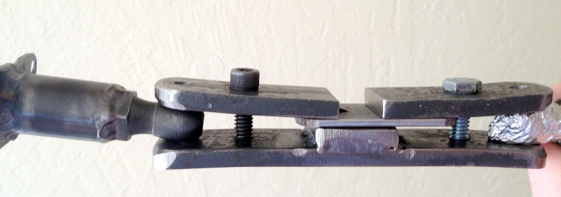
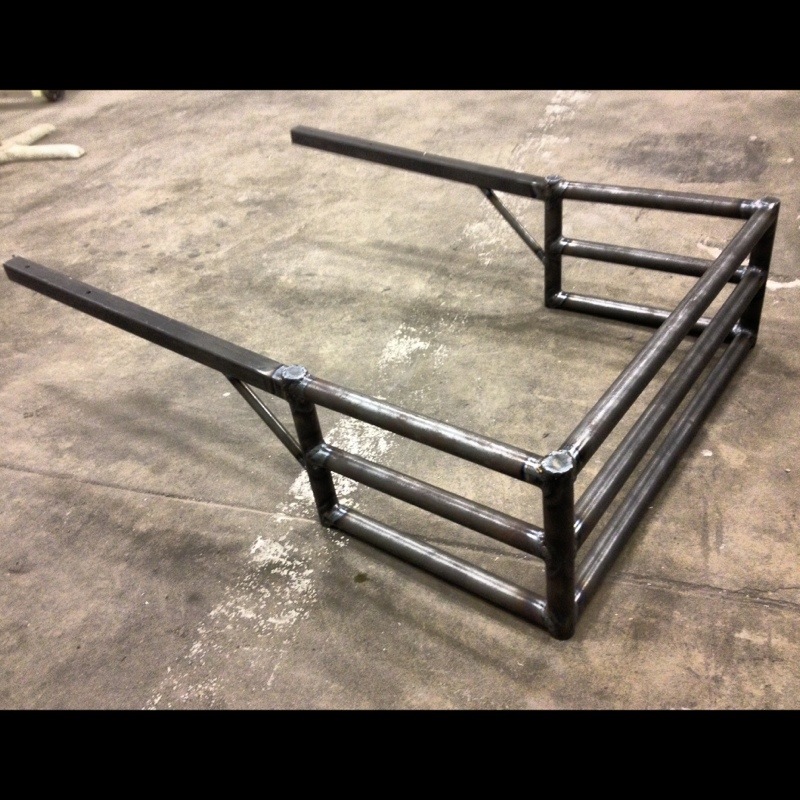
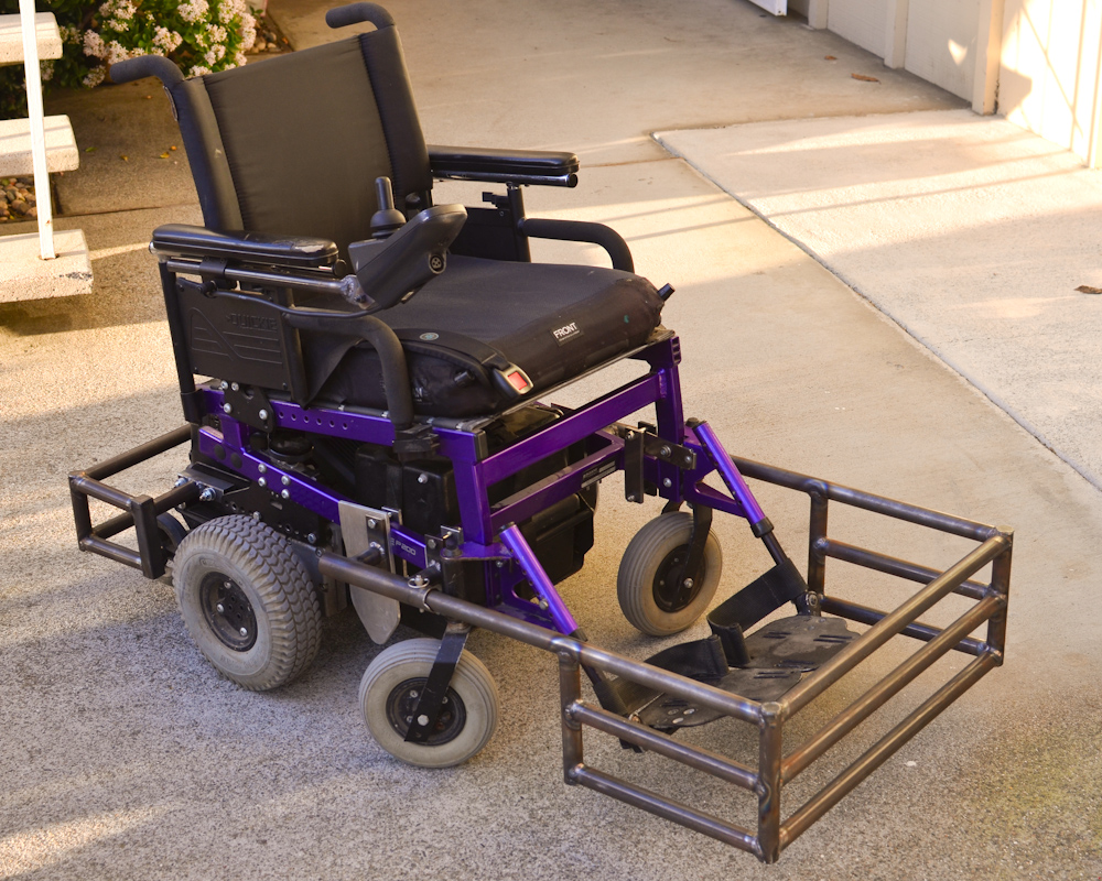
An extra benefit of all of this is that by using a round tube I was able to find a source for telescoping sizes of tube to let the guard slide into place securely. In place of four inconvenient screws to secure the guard, V3 just has a quick release pin.

You can see that I also used the guard mount to hold a side guard in place. That was an easy way to go, and I think it’s going to be sufficient to keep the ball from getting trapped. The worst part of this was trying to get the spacing between the two mounts at a close match to the guard tubes. I’ll be thinking about how to make that easier.

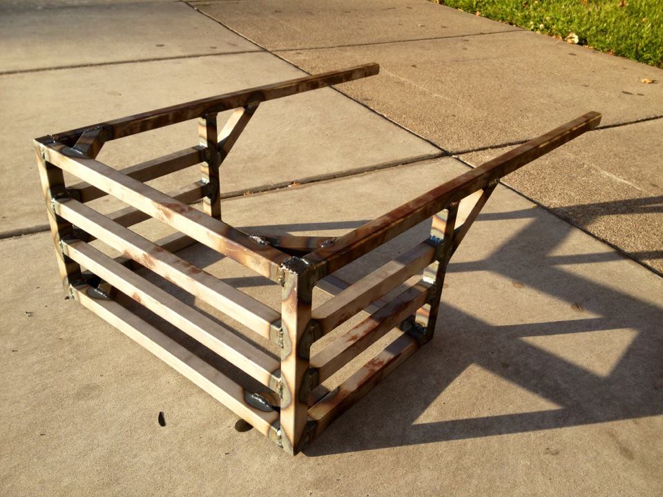
The player who owns this chair also wanted a rear guard. This is an allowed attachment that protects the battery box and anti-tip wheels, but also provides a strong and predictable surface for blocking and striking the ball. I’ve never built one before, so I’ll be watching closely to see how this one works out.

Each of the P200’s that I rebuild for soccer gets re-adjusted so that the driver’s center of gravity is placed right over the drive wheels. This improves traction and helps a lot for pivoting to hit the ball… the drawback is that it becomes far to easy to pop wheelies. This wastes time, makes control much more difficult, and can be really unsafe if the chair starts to run up and over the ball. All of the chairs that I’ve reconfigured to be so balanced so far have received additional anti-wheelie casters in the back. This keeps the front of the chair down, and greatly improves handling for the players.

Unfortunately, the same way that the V1 guard mounts were a product of what I was able to do with hand tools in an apartment’s kitchen, the anti-wheelie casters have been attached to the chairs in a primitive way. I use a piece of steel L-stock bolted to the back with two screws, and it takes some good hands to get the wheel on and off quickly. Most of the volunteers at practice struggle with it at first, and I’m probably only good at it because I used to do it three or four days per week when Kendra was training.

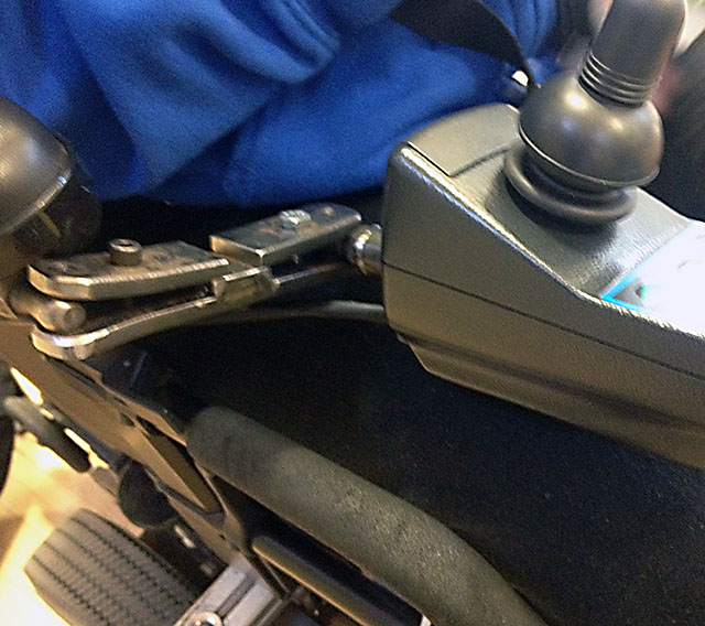
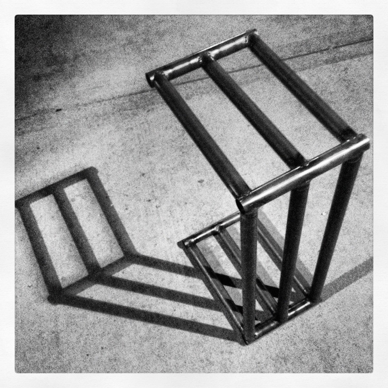
I’ve tried a couple of iterations of new attachments before, but nothing I’ve been happy with. I think that putting the wheel into the rear guard is as close as I’ve come to making it easy and strong. Here’s a detail view of how the wheel is attached:

When somebody’s sitting in the chair that wheel is almost an inch off the ground, though it’s almost touching the ground in this picture. The caster is screwed into the end of a tube that sits inside one of those telescoping sections, and there’s a screw that threads into the outer piece and pinches the inner piece. So far I’ve been able to drive the chair around over curb cuts and real-world terrain without getting stuck on anything that wasn’t an obvious problem. The next time I do this I’ll be looking for a way to have the retracted position a bit higher to be more sure that can’t happen.

That’s my latest! I’m really happy that I have a TechShop membership that allows me to have access to the right tools for the job so that I can do all of this stuff. I hope you’ve enjoyed reading about it.


Goofy photo technique

Goofy photo technique

I recently read about how out facial features (like all things) take on a distorted perspective as we get closer or farther away. Getting closer will make your nose bigger, and anything farther from the lens smaller. It isn’t just your nose- it’s whatever is closest to the lens that looks bigger.(I think this technique may be used in certain magazines that promote unrealistic body images) Things might look interesting when a wide angle lens is used to allow you to get closer, but they don’t look normal.

I don’t usually use image editing programs like photoshop, but I had the idea, “what if I pasted a close-up head onto a more normally proportioned body?”

Here’s the result:

20121130-153818.jpg

Another soccer guard (3)

Another soccer guard (3)

Here’s a picture of my setup for how I’m able to (relatively) quickly bang out some bars for the soccer guard.

20121113-231900.jpg

When I set up the mill like this and use the vertical tube to orient and locate the horizontal tube, I just need to drive the X axis to the predetermined spot while squirting a little coolant, and all of the tubes I make are the same within a few hundredths of an inch. It’s not an accurate way to do it from setup to setup, but it’s good enough for what I need, and it gets the gaps tight enough for easy TIG welding.

It could be better, but with the tools I have at Techshop and the size of batches I do, this is working well enough for me right now.

Another soccer guard (2)

Another soccer guard (2)

20121029-105944.jpg

There it is- the new guard. I haven’t put it onto a chair yet, but I have a good feeling about it. I think I got things fairly straight. A jig to hold everything during tack welding would have made things go together easier. It also would have been nice of I had been able to mill the edges of the inside edge of where the horizontal tubes come together at 90 degrees. I had to grind off the interfering edges, and any imprecision created a gap that I had to bridge with filler. It’ll be strong enough, I think, but would have been easier with a nice tight fit all around.

It weighs 10.8 pounds, about two pounds more than the World Cup guard. I don’t have access to a CAD system that will calculate rotational inertia for me (and I don’t feel like doing it by hand for), but I suspect that the new design isn’t quite as good in that respect. Regardless, this is about $80 worth of steel, compared to $300 for the cheapest commercially available guard. It also has a much more square tip, allowing the player to hit the ball with a spot closer to the end of the guard where the speed is highest.

Another soccer guard

Another soccer guard

I’ve been working on a design for the team that will be somewhat light weight, and not as expensive, time consuming, or fragile as the one I made for Kendra.
Aircraft Spruce sells some 1″ diameter tube for $2.80 per foot, compared to $3.50 per foot for the smaller diameter tubing I used before, and I get to use less of it. I also don’t use any of the square tubing that costs $10.75 per foot.

More important than the cost of the tubes, the old design had a lot of semi-precise milling required, and had almost 50 welded joints. This design has simpler tube preparation and less than half the welds. Access to the joints is better, so it’s a little easier to get the torch into all the required angles. The tubes are much stronger than the 1/2″ tubes, so I don’t expect this guard to get dented in from any normal hit.

The guard weighs about half a pound to a pound more than the one I designed for Kendra, and a lot less than the guard I posted on September 24th. It remains to be seen if it gives a good hit on the ball, but I’m optimistic.

20121023-212647.jpg